Today, there are a large number of different energy sources that people use. The main ones are, of course, coal and, but after all, they will someday end. Unfortunately for many, but there are not so many reserves of these hydrocarbons. According to rough estimates of scientists, gas and oil on our planet will end in 50 years, and coal in 400-500. Of course, such forecasts are made taking into account the fact that there will be no new deposits discovered, but still it is worth thinking about, and what if this happens ?!
 Of course, wave power plants whose efficiency is of decent importance have a number of advantages that make them more promising over hydrocarbons. The main one is considered to be the efficiency that has high rates. It is also worth noting that the float wave power station can also serve as a wave suppressor. Thanks to this use, it is possible to secure the shores of reservoirs that have strong tides. Waves can also protect the state’s maritime borders, but this will require a slight improvement.
Wind Farm Construction
During the construction of a wind farm, the following factors for generating electrical energy must be considered:
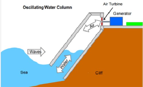
- It is required to take into account the kinetic energy of the waves. When a wave power plant enters the pipe, water exerts pressure on the inside, which is driven and generates energy. Also, this process can be carried out using pressure, which is water, pushing air out of the hollow chamber.
- The energy obtained from rolling the surface. In such cases, special sensors called floats are installed on the water surface. They track the profiles of each wave and convert the swing to electrical energy.
Fortunately, the PVES scheme is simple, therefore, construction and commissioning do not have to spend large sums of money, while the efficiency of the tidal power station allows it to be used even for large coastal cities.
Conclusion
Of course, like other alternative methods of generating electric energy, this method has not been fully studied and developed, but the process is proceeding at a very good pace. Today, even conversion cannot compete on an equal footing with hydrocarbon sources, but all alternative methods should continue to be explored. Not so long ago, Russia began to develop a project for obtaining energy from a wind farm, but the country has great potential and opportunities that only need to be fully realized.
A wave power plant is a power plant located in a water natural environment in order to obtain electricity from the kinetic energy of water masses. The oceans have tremendous energy, but so far the person has just begun to master it. It is this task that wave power plants perform.
Principle of operation
The principle of operation of a wave power plant is based on the conversion of the kinetic energy of the waves into electrical energy. There are several ways to arrange such stations different in principle of operation and design.
Wave power plants in Russia
In Russia, as in all countries with access to the sea coast, after many years of calm, interest in renewable energy sources is returning, and wave power plants are among them.
The first power plant in our countrybased on wave energy conversion, built in  2014 in the Far East in the Primorsky Territory on the Gamow Peninsula. This is a universal station, it is capable of converting not only the energy of directed water masses, but also the energy of natural tides.
The relevant ministries of our country, together with the leadership of the state, have developed a green energy development plan until 2020, according to which alternative energy sources will make up 5% of the total amount of electricity generated in the country. This plan also provides for the further development of wave power plants.
Wave power plants in the world
The world's first wave power plant appeared in 1985 in Norway, with a capacity of 500 kW.
The world's first industrial power plant using wave energy to produce  electric energy, commonly considered Oceanlinx in Australia. It began its operation in 2005, then it was reconstructed, and in 2009 the station started operating again. The operation of the station is based on the principle of “oscillating water column”. The power of the installation is now 450 kW.
The first commercial wave power plant began operations in 2008 in Agusador, Portugal. This is a pioneer installation that uses directly the mechanical energy of the wave. The work of the station is based on the principle of “oscillating body”. The British company Pelamis Wave Power developed the project, the station's capacity was 2.3 MW, and there is the possibility of increasing the capacity by mounting additional sections.
In the UK, built the world's largest wave power station, Wave Hub, located on the Cornwall Peninsula. The power plant is equipped with 4 generators with a capacity of 150 kW each. The work of the station is based on the principle of “oscillating body”.
Why is it profitable?
AT the existing world people are increasingly thinking about the need for renewable energy when generating electricity. One such option is the energy of sea waves. Given the fact that the oceans have huge potential, whose energy can provide almost 20% of the required amount of energy consumption, the development of "green"  energy is very relevant in our time.
This can be explained by the following reasons:
- The natural resources of the planet are on the verge of depletion, the reserves of traditional energy sources: coal, oil and gas - are coming to an end.
- Nuclear power because of its potential danger has not received proper distribution.
- Green energy does not harm the environment and is renewable.
- The potential of wave power plants is estimated at 2.0 million MW, which is comparable in power to a thousand operating nuclear power plants.
Scientists around the world continue to work on improving methods for converting the energy of ocean waves, and the above reasons are an important argument for continuing this research.
Pros and cons of using
Any unit always has positive and negative aspects of its use, and it is the ratio of these parameters that determines the appropriateness of its use. Wave power plants are no exception, consider the pros and cons of using this energy source.
The advantages of using include:

The disadvantages of this type of power plants include:
- Low power of generated energy;
- Unstable nature of work caused by atmospheric phenomena in the environment;
- May endanger the operation of vessels and commercial fishing.
The above “cons” of use are gradually losing their relevance, scientists and designers continue their work. The development of new, more powerful generators allows you to receive a greater amount of electrical energy, with the same initial parameters of the primary energy, which is the energy of the waves. The tasks of transferring the received energy over long distances are being solved.
The waters of the oceans hide innumerable wealth, the main of which, perhaps, are unlimited sources of energy in the form of sea waves. For the first time, the use of the kinetic energy of rolls roll ashore was thought of in the 18th century in Paris, where the first patent for a wave mill was presented. Now technology has stepped far forward, and with the joint efforts of scientists, the first commercial wave power station was launched, which began to be operated in 2008.
Why is it profitable?
It's no secret that natural wealth is on the verge of exhaustion. Reserves of coal, oil and gas - the main energy sources - are coming to an end. According to the most optimistic forecasts of scientists, reserves are enough for 150-300 years of life. Nuclear power also did not live up to expectations. Large capacity and productivity pays off the costs of construction, operation, but the problems of landfill and environmental damage will soon force to abandon them. For these reasons, scientists are looking for new. Wind and solar power plants are already operating. But for all their merits, they have a significant drawback - low efficiency. It will not be possible to satisfy the needs of the entire population. Therefore, new solutions are needed.
A wave power plant uses the kinetic energy of the waves to generate electricity. According to the most conservative estimates, this potential is estimated at 2 million MW, which is comparable to 1000 working at full capacity. nuclear power plantsand about 75 kW / m falls on one meter of the wave front. In this case, there is absolutely no harmful effect on the environment.

General scheme of work
Wave power plants are called floating structures that are capable of converting the movement of waves into electric and transmitting it to the consumer. At the same time, they try to use two sources:
- Kinetic reserves. Sea shafts pass through a large diameter pipe and rotate the blades, which transmit the force to the electric generator. The pneumatic principle is also applied - water, penetrating into a special chamber, displaces oxygen from there, which is redirected through the channel system and rotates the turbine blades.
- Rolling energy. In this case, the wave power station acts as a float. Moving in space along with the wave profile, it makes the turbine rotate through a complex system of levers.
Different countries use their own technologies for converting the mechanical motion of waves into electricity, but the general scheme of action is the same.

Disadvantages of wave power plants
The main obstacle to the widespread introduction of wave power plants is their cost. Due to the complex design and complex installation on the surface of sea waters, the cost of introducing such installations into operation is higher than the construction of nuclear power plants or thermal power plants.
In addition, there are a number of other shortcomings, which are mainly associated with the emergence of socio-economic problems. The thing is that large float stations create a danger and interfere with navigation and fishing - a float wave power station can simply force a person out of fishing zones. Environmental consequences are possible. The use of installations significantly extinguishes sea walls, makes them smaller and prevents them from breaking ashore. Meanwhile, the waves play important role in the process of gas exchange of the ocean, cleaning its surface. All this can lead to a shift in the ecological balance.
Positive aspects of wave power plants
Along with the shortcomings, a wave power plant has a number of advantages that have a positive effect on human activities:
- installations, due to the fact that they extinguish the energy of the wave, can protect coastal structures (moorings, ports) from destruction by the power of the ocean;
- electricity is generated at minimal cost;
- high wave power makes wind farms economically more profitable than wind or solar power plants.
Water reserves are also possessed by land waters, mainly rivers. The construction of stations on bridges, crossings, moorings is a prospect for the development of this area of \u200b\u200belectricity generation.

Problems to be Solved
The main task facing the scientific community now is to improve the design, which will reduce the cost of electricity generated by wave power plants. The principle of work should remain the same, but new technologies and materials will already be used to create plants.
The average wave power is 75-85 kW / m - this is the range most stations are tuned to. However, during a storm, the strength of sea shafts increases several times and there is a danger of destruction of installations. Already more than one blade was wrinkled or bent after a storm. To solve this problem, scientists reduce the specific power of the waves by artificial methods. One of the problems is that the massive use of wave stations will lead to climate change. Electric energy is generated by the rotation of the Earth (this is how waves form). Widespread use of stations will cause the planet to rotate more slowly. A person will not feel the difference, but it will destroy a number of currents that play an important role in the heat transfer of the Earth.

The world's first experimental wind farm
The first wave power station appeared in 1985 in Norway. Its power was 500 kW, and she herself was a prototype. Its operating principle is based on cyclic compression and expansion of the medium:
- a cylinder with an open bottom is immersed in water so that its edge is below the trough of the wave - its lowest point;
- periodically running water compresses the air in the internal cavity;
- upon reaching a certain pressure, a valve opens, which allows compressed oxygen to pass to the turbine.
Such a power plant generated 500 kW of energy so that it was enough to confirm the effectiveness of the plants, which contributed to their development.

The world's first industrial power station
The world's first installation industrial scale considered to be Oceanlinx in the Port Kemb area of \u200b\u200bAustralia. It was commissioned in 2005, but then it was sent for reconstruction and in 2009 it started working again, due to which both tidal and wave power plants are now used in the region. Its principle of action is as follows:
- Waves periodically run into special chambers, causing air to compress.
- Upon reaching critical pressure, the generator rotates through a network of channels.
- To capture the movement and strength of the waves, the turbine blades change their angle of inclination.
The power of the installation was about 450 kW, although each section of the station is capable of generating from 100 kW * h to 1.5 MW * h of electric energy.
The world's first commercial wind farm
The first commercial wave power plant was launched in 2008 in Agusador, Portugal. Moreover, it is the first installation in the world that uses directly the mechanical energy of the wave. The project was prepared by the English company Pelamis Wave Power.
The structure includes several sections that are released and raised along with the wave profile. The sections are pivotally attached to the hydraulic system and actuate it during movement. The hydraulic mechanism causes the generator rotor to rotate, which generates electricity. The wave power plants used in Portugal have pros and cons. The advantage of the installation is its high power - about 2.25 MW, as well as the possibility of installing additional sections. The drawback of installing the system is one - there are difficulties with the wires to the consumer.
Russia's first wave power plant
In Russia, the first wind farm appeared in 2014 in the Primorsky Territory. The team of scientists from the Pacific Oceanological Institute of the Far Eastern Branch of the Russian Academy of Sciences was engaged in the development. The installation is experimental in nature. Its peculiarity is that it uses the energy of not only waves, but also tides.
In Moscow, the construction of a research laboratory is planned, which will develop and create the first domestic float station. Perhaps after this, wave power plants in Russia will also have industrial or commercial purposes.
A power plant is designed to generate electricity by using wave energy. The device comprises a floating housing with an electric generator and floats located on a horizontal shaft. On spaced pontoons, flyovers are transversely parallel to each other with supports under the shaft. On each shaft, floats in the form of hollow half-cylinders equipped with additional load and a volumetric protrusion are installed with a minimum clearance. In this case, the nearest parallel shafts are interconnected by a gear transmission. Shafts located on the same line on opposite sides of the pontoon with the drive mechanisms to the electric generator are also interconnected and have a common gear transmission, gearbox and electric generator. The design of the power plant allows you to get an increase in power removed from 1 m 2 of water. 4 C.p. f-py, 4 ill.
The invention relates to energy, in particular for generating electricity by using the energy of sea waves due to the resulting vertical rises and decays of waves. Known wave power plant, and.with. N 1373855 F 03 B 13/12, containing a floating casing with an electric generator, an air turbine to wave receiving chambers with floats. The cameras are made in the form of glasses, the open end of which is submerged under the water level. Moreover, to increase the efficiency, each chamber is equipped with an additional air turbine and a hydraulic pump connected to the float by means of an endless chain transmission. The main disadvantage of this installation is the limited power associated with the slow rise of the float, equal to the rise of the wave, and the fact that a limited buoyancy from the float, equal to half the volume of the float, acts on the circuit, since specific gravity the float is 0.5 g / cm 3. A large number of mechanisms and transmission devices complicates the installation and leads to significant power losses, reducing the effect of using the float. Known wave power plant (RF patent N 2049925, CL 6 F 03 B 13/12, 6 F 03 B 13/22 from 02/06/1992), containing a floating casing with an electric generator, an air turbine and wave receiving chambers in the form of immersed in water the open end of the cups, provided with L-shaped floats installed on a horizontal shaft with the possibility of one-sided rotation, with one of the protrusions of the float is longer or heavier than the other, all shafts are interconnected, the boost gearbox is connected to the latter and the shaft of the air turbine by means of overruns couplings, and the turbine shaft is connected to an electric generator. The main disadvantage of this wave power plant is also low efficiency and design complexity. This is due to the fact that due to the short-term effect of the wave on the compressed air in the chambers, it is not possible to transfer all the air compressed in the chamber to the air turbine, and with an increase in the cross section of the ducts and the turbine itself, the air pressure in the chamber and, accordingly, the removed power from the turbine will decrease. The L-shaped form of the float does not allow efficient use of space in terms of increasing the buoyancy force and creates even greater hydraulic resistance during the rotation of its protrusions. In addition, the design of a wave power plant using compressed air energy is very difficult to manufacture and operate and requires large capital costs for the manufacture of a turbine. The wave power plant according to the patent of the Russian Federation N 2049925 adopted as a prototype. The objective of the invention is to simplify the design and increase the power of the wave power plant. This is achieved by the fact that in a wave power plant containing a floating body with an electric generator, floats located on a horizontal shaft with the possibility of one-sided rotation, occupying an unstable equilibrium in water, which becomes an unbalanced state and accelerated rotational motion at the moment the float is completely immersed, increases the gearbox connecting a shaft with an electric generator, a floating body made in the form of at least two narrow pontoons connected in width and provided with transversely parallel to each other trestles, coaxially mounted brackets with supports under the shaft along the bottom of the flyover, floats located between all supports in series with minimum end gaps, eliminating the jamming of the floats during their relative rotation, at the output ends of the shafts there is a gear connected directly to the gear on the input shaft of the gearbox or through an overdrive gear, the float is made in the form of a hollow sealed half-cylinder and is equipped with an additional load and a volumetric protrusion located on the side opposite to the axis of the side in the form of an additional float, while the moment created by the weight of the volumetric protrusion is more (about 5-10%) of the moment created by the additional load, and the moment created by the buoyant force when one volumetric protrusion is immersed in water is greater than the moment created by the weight of the volumetric protrusion, unbalanced effects on the float of water and air flows and the friction forces at the moment the float begins to rotate. In this case, the output ends of adjacent flyover shafts are paired or more interconnected by gearing gears and the installation of a common gearbox and electric generator, and the floats on symmetrical shafts are interconnected, the output ends of coaxially located flyover shafts placed in one line are interconnected and equipped with a common gear transmission, gearbox and electric generator, the volumetric protrusion of the floats is made integral with the semicylinder by lengthening the circumference of the semicylinder, the front surface of the volumetric protrusion along the rotation of the float is made in the form of a narrowing wedge. In FIG. 1 shows a general view of a wave power plant; FIG. 2 shows a top view, FIG. 3 shows a float separately, and in FIG. 4 its surface. It is indicated - the angle of rotation of the float to its current position, Q о - buoyant force acting on the float in the initial position, P - weight of the float, h p - shoulder of the force of the weight of the float, C в - point of the center of mass of water in the volume of the immersed part of the float , Q is the buoyant force in the current position, h in is the shoulder of the buoyant force, P s is the weight of the bulge, P d is the weight of the additional load, Y st is the distance from the axis O to the center of mass of water in the volume of the submerged part of the float (for sector with angle ![]() Y sp is the distance from the O axis to the center of mass of the float, h s is the shoulder of the weight force of the bulge, h d is the shoulder of the weight of the additional load, l is the length of the float, R is the outer radius of the float. The wave power plant consists of a floating hull made in the form of at least two narrow pontoons spaced apart from each other in width (Fig. 1 shows 3 pontoons - 1, 2 and 3), interconnected by beams 4 and 5. Pontoons 1 and 3 made in the form of a hollow sealed pipe, and the middle pontoon 2 has a box shape to accommodate the drive mechanisms. On the pontoons installed across them and parallel to each other flyovers 6, resting their ends on the pontoons. Along each overpass 6, a bracket 7 is mounted coaxially from the bottom with supports under the shaft 8. Between all the supports of the brackets 6, floats 9 are mounted on the shaft with the possibility of one-way rotation (due to the use of overrunning couplings or ratchet mechanisms). The floats 9 are arranged sequentially on the shaft with minimal end gaps, eliminating the jamming of the floats during their relative rotation from temperature and force deformations. At the output ends of the shafts 8, gears 10 are mounted, which are engaged directly with the gears (not shown in FIG.) On the input shaft of the reduction gears 11 or through an additional raising gear (not shown in FIG.). The gear wheel 10 simultaneously performs the role of a flywheel. The output shaft of each gearbox 11 is connected to the shaft of the electric generator 12 (gearbox 11 is installed if necessary, transmission to the generator without gearbox is possible). The floats 9 (see Fig. 3) are made in the form of hollow sealed half-cylinders. Moreover, they are provided with a volumetric protrusion 13 (above the axis OX), made in the form of a separate element or at the same time with the half-cylinder, as shown in FIG. 3 (the volumetric protrusion is made by lengthening the circumference of the half-cylinder by an angle from the axis OX) and the formation of an additional sector. An additional load 14 is installed on the opposite side inside the float so that the moment created by the weight of the volumetric protrusion 13 is equal to or greater (by about 5-10%) of the moment created by the additional weight 14, and the buoyancy force acting on one volumetric protrusion 13 when immersed in water, it must create a torque greater than the moment created by the weight of the volumetric protrusion, the chaotic and unbalanced impact on the float of water and air flows and the frictional forces acting at the moment the float begins to rotate. The volumetric protrusion 13 is the initiating element that displays the float from an unstable equilibrium to an unbalanced state with an accelerated rotation of the float (somersault) when the float is completely immersed in water. The dimensions of the wave power plant, the number of pontoons and flyovers with floats depend on the planned power take-off. Moreover, to ensure greater uniformity of rotation of the generator, as well as reducing the number of used drive mechanisms (gears, gearboxes, couplings, etc.), the output ends of adjacent racks shafts are paired or more interconnected by gearing gears at the output ends of the shafts between themselves with the installation of a common gearbox, an electric generator and a step-up gear train, and the floats on the kinematically connected shafts are arranged symmetrically relative to the plane passing in the middle of the distance between the shafts. In this case, the volumetric protrusions of the floats on one shaft will be located on the opposite side with respect to the location of the volumetric protrusions of the floats on the other shaft. This arrangement of floats provides rotation of kinematically connected shafts in different directions. When the number of pontoons is more than two, to ensure greater uniformity of rotation of the electric generators and to reduce the number of used mechanisms of drives and electric generators, overpasses and shafts on adjacent pontoons are placed in one line. In this case, the output ends of the flyover on adjacent pontoons are connected to each other (using a coupling) using one common gear at the output end of one of these shafts, a common overdrive gear, a common gearbox and an electric generator (as shown in Fig. 1). To reduce the resistance of water when the float is immersed in water at the moment when it makes a rotational movement from the extreme upper position (after somersault), the front surface 15 in the direction of rotation of the float is made in the form of a narrowing wedge (Fig. 4). The floats 8 are mounted on the shaft with a clearance and transmit torque to the shaft using an overrunning clutch consisting of a wedge-shaped curved space 16 (formed by a curved surface 17 of the recess of the shaft and the cylindrical surface of the bore of the float) and spring-loaded fingers 18 mounted inside the wedge-curved space 16 It is possible to couple the floats with the shaft using a ratchet mechanism consisting of a ratchet wheel fixed to the shaft and a dog mounted on the float (in FIG. not shown). Moreover, to reduce the length of the shafts, the ratchet wheel and the dog should be placed inside the groove of the float, made coaxially with the holes of the float on the side of one or two ends of the float. To ensure guaranteed retention of the floats at the time of the wave from the turn until they are completely flooded and thereby create the maximum potential energy of the submerged float, as well as expanding technological capabilities in terms of eliminating the need for very accurate manufacturing of floats, it is advisable to ensure that the moment created by the weight of the volume element , obviously exceeded the moment created by the weight of the additional load. In this case, to keep the floats from turning in the opposite direction under the influence of this difference in moments at the level of the rear surface 19 of the floats 9, spring-loaded movable stops 20 are pivotally mounted on the fixed rods 21 connected to the racks with a slight overlap of the rear surface of the float. Above the movable stops 20, fixed stops 22 are mounted on the rods, located outside the rotation zone of the float and holding the movable stops 20 from rising upwards. Since when the float is immersed in water before the flooding of the volumetric protrusion, the unbalanced moment acting in the opposite direction on the float is insignificant, then the force of the impact of the float from below on the movable stop 20 is insignificant. This allows the stops 20 to be made small in weight and volume and to use a spring with a small compression force. Therefore, with the working rotation of the float and its impact on the movable stops 20, already from above, they easily rotate, immersed in water, and do not have much resistance to the floats. The fixed stops 22 can be made directly in the hinges of the movable stops 20 in the form of known designs of limiters rotation. If the moments created by the volumetric protrusion and the additional load are equal, the use of a movable stop 20 and a fixed stop 22 can be excluded. But for this it is necessary to ensure a gradual increase in the volume of the right part of the float from the OY axis, for example, due to a smooth increase in the length of the float. When the right part of the float is immersed in water, a greater buoyant force will act than in the left, which will ensure a guaranteed rotation of the float towards the volumetric protrusion. But in this case, it is impossible to ensure the maximum supply of potential energy of the float, and its rotation will be adequate to raise the water level in the wave. The floating body is equipped with extensions 23 with the possibility of changing their length (for example, using a winch). This allows you to change the position of the housing relative to the direction of the waves in order to provide a smoother loading of the shafts with torque from the floats located at an angle to the wave front. There are other options for changing the angular position of the body, for example, using an air or water keel. To adjust the position of the floats relative to the water level during the installation of the power plant, jacks and gaskets are used at the supports of overpasses. In this case, it is advisable to install with the maximum location of the floats relative to the water level, and adjust the housing draft by pumping or pumping in pontoons. It is possible to use additional pontoons for this by raising or lowering them into water at a certain depth. To shelter the equipment from atmospheric precipitation and create normal climatic conditions, a covered room is provided in the work of the operating personnel 24. The box-shaped pontoon 2 is closed from above by hatches (not indicated in Fig.). The operation of the wave power plant is as follows. In the initial position, when there are no waves, all floats 9 occupy the lowest position according to FIG. 3, while they may or may not touch the water and may even be slightly immersed in water (to the water level at which, during operation, the float freely falling from the extreme upper position creates an unbalanced moment even when part of the float is immersed in water to this level, and the float freely returns to its original position, being partially flooded.The difference in moments M from the weight of the volumetric protrusion 13 and the additional load 14 presses the float 9 against the movable stop 20, and that in turn is pressed against the fixed stop 22. When waves form, "at an acute angle to the axis of the shafts, the floats are alternately immersed in water (flooded by the wave). In this case, a buoyant force Q is created equal to the weight of water in the volume of the submerged float (according to Archimedes' law). Since the buoyant forces acting on both sides of the OY axis are equal, then the resulting buoyant force Q passes vertically upward through the axis of rotation of the float and does not create torque when immersed and float all the way to the OX axis. The force of the weight of the float P also passes through the axis OX, only downward, and does not create a torque, with the exception of the above moment M, created by the difference in moments from the weight of the volume protrusion 13, and the weight of the additional load, which is balanced by the reaction R of the support from the stops 20 and 21 . When the float dives above the OX axis, the volumetric protrusion 13 is flooded, resulting in an additional torque that exceeds the difference M in moments from the weight of the volumetric protrusion and additional load. As a result of this, the float begins to turn, jumps to a position of unstable equilibrium and tends to flip and jump out of the water with acceleration. The buoyant force acting on the left side of the OY axis will rapidly decrease, and on the right side, the maximum buoyant force equal to the weight of the displaced water in the volume of half the cross-section of the float acts throughout the entire rotation of the float from its original position to the angle O \u003d 90 o. When turning through the angle O \u003d 90 o, the buoyant force on the left side becomes equal to 0, and starting from the angle \u003d 90 o, the buoyant force on the right side decreases and becomes \u003d 0 when the rear surface 19 does not reach the axis OX with back side from the axis OY. All this happens instantly, with acceleration, the float emerges completely from the water with acceleration. This effect is created due to the shape of the float. During the rotation, the left side of the float constantly crosses the position of unstable equilibrium and, as it were, “pumps up” the volume on the right side, completely compensating for the outlet from the water of the float during the entire rotation by an angle of 90 o, and therefore preserving the amount of buoyancy force on the right side. It is known from mechanics that when a force constantly acts on a body, it moves with acceleration. But such a sharp turn of the float at first is hindered by the inertia force and resistance of the shaft drive system, gears, gearbox and electric generator, which only begin to slow rotation first. Due to the simultaneous action of several floats, sufficient moment is created for the rotation of the shaft. Initially, the shaft speed less speed the rotation of the floats that they would have had a somersault. The floats act on the shaft and rotate at the speed of the shaft. At the same time, they do not have time to completely get out of the water, as the wave level begins to fall, and the floats return back to their original position. The shafts continue to rotate by inertia and from the fact that other floats act on them, and do not prevent the previous floats from returning to their original position due to the presence of overrunning clutches or a ratchet mechanism. While some floats are idling on the shaft, other floats are making an active stroke at this time, while other floats are in an intermediate state. As the shaft revolutions increase, the floats increase the shaft rotation speed. At the same time, with each revolution, floats more and more emerge from the water, and the speed of the shafts approaches the speed of the somersault of the floats in a state free from the shaft. The floats already have time to fully emerge from the water before the wave level begins to fall and occupy the highest position. At this moment, the front surface 15 of the floats acts on the movable stop 20, squeezes it down and immersed in water. When the wave level drops, the floats continue to rotate to their original position adequately to the wave decline. This is facilitated by the difference in moments M from the weight of the bulge and the weight of the additional load. The shafts are already rotating at a faster speed than the floats turning towards the starting position. In this case, due to the inertia of the movement, the floats slip through the initial position and release the movable stop 20, which returns under the action of the spring to its original position. At this time, because of the difference in moments M, the floats oscillate back to their original position and abut against the movable stop 20 interacting with the fixed stop 22 and stop in the initial position. Next, the process is repeated for each float with a frequency of wave incidence, depending on the wave amplitude: the higher the wave, the longer period. When the shafts rotate, the gears 10, mounted on the output end of the shafts, transmit the torque directly to the gear on the input shaft of the gearbox 11 (or through an additional boost gear). From the gearbox 11, the torque is transmitted to the generator. In the rotation of each shaft in the wave power plant, there comes a moment when, from the influence of some last group of floats, the shaft accelerates to such an extent that its rotation speed becomes equal to the average speed of rotation of the floats during a somersault. The floats cease to act on the shaft for a moment, and the shaft again begins to lose speed. The floats again begin to act on the shaft and add torque to it. The shaft accelerates again, then decelerates again; thus, the shaft rotation speed is maintained close to the speed of rotation of the float with a free somersault. To calculate the power N from a wave power plant, it is first necessary to calculate the torque generated by one float. To simplify the calculations, we assume that the air space inside the float starts from the axis of rotation, i.e. we do not take into account the presence of a hub and a hole in the float (at the same time, we compensate for a very slight increase in the torque from the buoyant force by the fact that the calculations will not take into account the torque created by the buoyant force acting on the bulge when it is flooded with a wave). Consider the current position of the float (Fig. 3), in which he had already made a rotation from the starting position by a certain angle. In this case, the flooded part of the float - half cylinder represents a sector with an angle of 180 o - (volumetric protrusion is not taken into account). The center of mass of this part of the sector will be located at point C in a radius dividing the sector in half, i.e. on the coal sector. From the OY axis this makes an angle. Another force of weight P acts on the float, the center of gravity C p of which is located at a radius passing along the axis of symmetry of the float (180 o: 2 \u003d 90 o) in the initial position. From the OY axis in the current position, this makes an angle. A formula is known from mechanics that relates the kinetic energy of rotational motion (T - T o) at an angle from \u003d 0 to work A, performed for the same rotation from 0 to: (T - T o) \u003d A, where
Y sp is the distance from the O axis to the center of mass of the float, h s is the shoulder of the weight force of the bulge, h d is the shoulder of the weight of the additional load, l is the length of the float, R is the outer radius of the float. The wave power plant consists of a floating hull made in the form of at least two narrow pontoons spaced apart from each other in width (Fig. 1 shows 3 pontoons - 1, 2 and 3), interconnected by beams 4 and 5. Pontoons 1 and 3 made in the form of a hollow sealed pipe, and the middle pontoon 2 has a box shape to accommodate the drive mechanisms. On the pontoons installed across them and parallel to each other flyovers 6, resting their ends on the pontoons. Along each overpass 6, a bracket 7 is mounted coaxially from the bottom with supports under the shaft 8. Between all the supports of the brackets 6, floats 9 are mounted on the shaft with the possibility of one-way rotation (due to the use of overrunning couplings or ratchet mechanisms). The floats 9 are arranged sequentially on the shaft with minimal end gaps, eliminating the jamming of the floats during their relative rotation from temperature and force deformations. At the output ends of the shafts 8, gears 10 are mounted, which are engaged directly with the gears (not shown in FIG.) On the input shaft of the reduction gears 11 or through an additional raising gear (not shown in FIG.). The gear wheel 10 simultaneously performs the role of a flywheel. The output shaft of each gearbox 11 is connected to the shaft of the electric generator 12 (gearbox 11 is installed if necessary, transmission to the generator without gearbox is possible). The floats 9 (see Fig. 3) are made in the form of hollow sealed half-cylinders. Moreover, they are provided with a volumetric protrusion 13 (above the axis OX), made in the form of a separate element or at the same time with the half-cylinder, as shown in FIG. 3 (the volumetric protrusion is made by lengthening the circumference of the half-cylinder by an angle from the axis OX) and the formation of an additional sector. An additional load 14 is installed on the opposite side inside the float so that the moment created by the weight of the volumetric protrusion 13 is equal to or greater (by about 5-10%) of the moment created by the additional weight 14, and the buoyancy force acting on one volumetric protrusion 13 when immersed in water, it must create a torque greater than the moment created by the weight of the volumetric protrusion, the chaotic and unbalanced impact on the float of water and air flows and the frictional forces acting at the moment the float begins to rotate. The volumetric protrusion 13 is the initiating element that displays the float from an unstable equilibrium to an unbalanced state with an accelerated rotation of the float (somersault) when the float is completely immersed in water. The dimensions of the wave power plant, the number of pontoons and flyovers with floats depend on the planned power take-off. Moreover, to ensure greater uniformity of rotation of the generator, as well as reducing the number of used drive mechanisms (gears, gearboxes, couplings, etc.), the output ends of adjacent racks shafts are paired or more interconnected by gearing gears at the output ends of the shafts between themselves with the installation of a common gearbox, an electric generator and a step-up gear train, and the floats on the kinematically connected shafts are arranged symmetrically relative to the plane passing in the middle of the distance between the shafts. In this case, the volumetric protrusions of the floats on one shaft will be located on the opposite side with respect to the location of the volumetric protrusions of the floats on the other shaft. This arrangement of floats provides rotation of kinematically connected shafts in different directions. When the number of pontoons is more than two, to ensure greater uniformity of rotation of the electric generators and to reduce the number of used mechanisms of drives and electric generators, overpasses and shafts on adjacent pontoons are placed in one line. In this case, the output ends of the flyover on adjacent pontoons are connected to each other (using a coupling) using one common gear at the output end of one of these shafts, a common overdrive gear, a common gearbox and an electric generator (as shown in Fig. 1). To reduce the resistance of water when the float is immersed in water at the moment when it makes a rotational movement from the extreme upper position (after somersault), the front surface 15 in the direction of rotation of the float is made in the form of a narrowing wedge (Fig. 4). The floats 8 are mounted on the shaft with a clearance and transmit torque to the shaft using an overrunning clutch consisting of a wedge-shaped curved space 16 (formed by a curved surface 17 of the recess of the shaft and the cylindrical surface of the bore of the float) and spring-loaded fingers 18 mounted inside the wedge-curved space 16 It is possible to couple the floats with the shaft using a ratchet mechanism consisting of a ratchet wheel fixed to the shaft and a dog mounted on the float (in FIG. not shown). Moreover, to reduce the length of the shafts, the ratchet wheel and the dog should be placed inside the groove of the float, made coaxially with the holes of the float on the side of one or two ends of the float. To ensure guaranteed retention of the floats at the time of the wave from the turn until they are completely flooded and thereby create the maximum potential energy of the submerged float, as well as expanding technological capabilities in terms of eliminating the need for very accurate manufacturing of floats, it is advisable to ensure that the moment created by the weight of the volume element , obviously exceeded the moment created by the weight of the additional load. In this case, to keep the floats from turning in the opposite direction under the influence of this difference in moments at the level of the rear surface 19 of the floats 9, spring-loaded movable stops 20 are pivotally mounted on the fixed rods 21 connected to the racks with a slight overlap of the rear surface of the float. Above the movable stops 20, fixed stops 22 are mounted on the rods, located outside the rotation zone of the float and holding the movable stops 20 from rising upwards. Since when the float is immersed in water before the flooding of the volumetric protrusion, the unbalanced moment acting in the opposite direction on the float is insignificant, then the force of the impact of the float from below on the movable stop 20 is insignificant. This allows the stops 20 to be made small in weight and volume and to use a spring with a small compression force. Therefore, with the working rotation of the float and its impact on the movable stops 20, already from above, they easily rotate, immersed in water, and do not have much resistance to the floats. The fixed stops 22 can be made directly in the hinges of the movable stops 20 in the form of known designs of limiters rotation. If the moments created by the volumetric protrusion and the additional load are equal, the use of a movable stop 20 and a fixed stop 22 can be excluded. But for this it is necessary to ensure a gradual increase in the volume of the right part of the float from the OY axis, for example, due to a smooth increase in the length of the float. When the right part of the float is immersed in water, a greater buoyant force will act than in the left, which will ensure a guaranteed rotation of the float towards the volumetric protrusion. But in this case, it is impossible to ensure the maximum supply of potential energy of the float, and its rotation will be adequate to raise the water level in the wave. The floating body is equipped with extensions 23 with the possibility of changing their length (for example, using a winch). This allows you to change the position of the housing relative to the direction of the waves in order to provide a smoother loading of the shafts with torque from the floats located at an angle to the wave front. There are other options for changing the angular position of the body, for example, using an air or water keel. To adjust the position of the floats relative to the water level during the installation of the power plant, jacks and gaskets are used at the supports of overpasses. In this case, it is advisable to install with the maximum location of the floats relative to the water level, and adjust the housing draft by pumping or pumping in pontoons. It is possible to use additional pontoons for this by raising or lowering them into water at a certain depth. To shelter the equipment from atmospheric precipitation and create normal climatic conditions, a covered room is provided in the work of the operating personnel 24. The box-shaped pontoon 2 is closed from above by hatches (not indicated in Fig.). The operation of the wave power plant is as follows. In the initial position, when there are no waves, all floats 9 occupy the lowest position according to FIG. 3, while they may or may not touch the water and may even be slightly immersed in water (to the water level at which, during operation, the float freely falling from the extreme upper position creates an unbalanced moment even when part of the float is immersed in water to this level, and the float freely returns to its original position, being partially flooded.The difference in moments M from the weight of the volumetric protrusion 13 and the additional load 14 presses the float 9 against the movable stop 20, and that in turn is pressed against the fixed stop 22. When waves form, "at an acute angle to the axis of the shafts, the floats are alternately immersed in water (flooded by the wave). In this case, a buoyant force Q is created equal to the weight of water in the volume of the submerged float (according to Archimedes' law). Since the buoyant forces acting on both sides of the OY axis are equal, then the resulting buoyant force Q passes vertically upward through the axis of rotation of the float and does not create torque when immersed and float all the way to the OX axis. The force of the weight of the float P also passes through the axis OX, only downward, and does not create a torque, with the exception of the above moment M, created by the difference in moments from the weight of the volume protrusion 13, and the weight of the additional load, which is balanced by the reaction R of the support from the stops 20 and 21 . When the float dives above the OX axis, the volumetric protrusion 13 is flooded, resulting in an additional torque that exceeds the difference M in moments from the weight of the volumetric protrusion and additional load. As a result of this, the float begins to turn, jumps to a position of unstable equilibrium and tends to flip and jump out of the water with acceleration. The buoyant force acting on the left side of the OY axis will rapidly decrease, and on the right side, the maximum buoyant force equal to the weight of the displaced water in the volume of half the cross-section of the float acts throughout the entire rotation of the float from its original position to the angle O \u003d 90 o. When turning through the angle O \u003d 90 o, the buoyant force on the left side becomes equal to 0, and starting from the angle \u003d 90 o, the buoyant force on the right side decreases and becomes \u003d 0 when the rear surface 19 does not reach the axis OX with back side from the axis OY. All this happens instantly, with acceleration, the float emerges completely from the water with acceleration. This effect is created due to the shape of the float. During the rotation, the left side of the float constantly crosses the position of unstable equilibrium and, as it were, “pumps up” the volume on the right side, completely compensating for the outlet from the water of the float during the entire rotation by an angle of 90 o, and therefore preserving the amount of buoyancy force on the right side. It is known from mechanics that when a force constantly acts on a body, it moves with acceleration. But such a sharp turn of the float at first is hindered by the inertia force and resistance of the shaft drive system, gears, gearbox and electric generator, which only begin to slow rotation first. Due to the simultaneous action of several floats, sufficient moment is created for the rotation of the shaft. Initially, the shaft speed less speed the rotation of the floats that they would have had a somersault. The floats act on the shaft and rotate at the speed of the shaft. At the same time, they do not have time to completely get out of the water, as the wave level begins to fall, and the floats return back to their original position. The shafts continue to rotate by inertia and from the fact that other floats act on them, and do not prevent the previous floats from returning to their original position due to the presence of overrunning clutches or a ratchet mechanism. While some floats are idling on the shaft, other floats are making an active stroke at this time, while other floats are in an intermediate state. As the shaft revolutions increase, the floats increase the shaft rotation speed. At the same time, with each revolution, floats more and more emerge from the water, and the speed of the shafts approaches the speed of the somersault of the floats in a state free from the shaft. The floats already have time to fully emerge from the water before the wave level begins to fall and occupy the highest position. At this moment, the front surface 15 of the floats acts on the movable stop 20, squeezes it down and immersed in water. When the wave level drops, the floats continue to rotate to their original position adequately to the wave decline. This is facilitated by the difference in moments M from the weight of the bulge and the weight of the additional load. The shafts are already rotating at a faster speed than the floats turning towards the starting position. In this case, due to the inertia of the movement, the floats slip through the initial position and release the movable stop 20, which returns under the action of the spring to its original position. At this time, because of the difference in moments M, the floats oscillate back to their original position and abut against the movable stop 20 interacting with the fixed stop 22 and stop in the initial position. Next, the process is repeated for each float with a frequency of wave incidence, depending on the wave amplitude: the higher the wave, the longer period. When the shafts rotate, the gears 10, mounted on the output end of the shafts, transmit the torque directly to the gear on the input shaft of the gearbox 11 (or through an additional boost gear). From the gearbox 11, the torque is transmitted to the generator. In the rotation of each shaft in the wave power plant, there comes a moment when, from the influence of some last group of floats, the shaft accelerates to such an extent that its rotation speed becomes equal to the average speed of rotation of the floats during a somersault. The floats cease to act on the shaft for a moment, and the shaft again begins to lose speed. The floats again begin to act on the shaft and add torque to it. The shaft accelerates again, then decelerates again; thus, the shaft rotation speed is maintained close to the speed of rotation of the float with a free somersault. To calculate the power N from a wave power plant, it is first necessary to calculate the torque generated by one float. To simplify the calculations, we assume that the air space inside the float starts from the axis of rotation, i.e. we do not take into account the presence of a hub and a hole in the float (at the same time, we compensate for a very slight increase in the torque from the buoyant force by the fact that the calculations will not take into account the torque created by the buoyant force acting on the bulge when it is flooded with a wave). Consider the current position of the float (Fig. 3), in which he had already made a rotation from the starting position by a certain angle. In this case, the flooded part of the float - half cylinder represents a sector with an angle of 180 o - (volumetric protrusion is not taken into account). The center of mass of this part of the sector will be located at point C in a radius dividing the sector in half, i.e. on the coal sector. From the OY axis this makes an angle. Another force of weight P acts on the float, the center of gravity C p of which is located at a radius passing along the axis of symmetry of the float (180 o: 2 \u003d 90 o) in the initial position. From the OY axis in the current position, this makes an angle. A formula is known from mechanics that relates the kinetic energy of rotational motion (T - T o) at an angle from \u003d 0 to work A, performed for the same rotation from 0 to: (T - T o) \u003d A, where ![]() where is the speed of rotational motion; M is the torque; I o - moment of inertia. To determine the work, we first compose the equation for torque. The equation of the moment acting on the float in the current position (when turning at a certain angle) M t \u003d Qh in - Ph p - P o h h o + P d h d \u003d M tren.
where is the speed of rotational motion; M is the torque; I o - moment of inertia. To determine the work, we first compose the equation for torque. The equation of the moment acting on the float in the current position (when turning at a certain angle) M t \u003d Qh in - Ph p - P o h h o + P d h d \u003d M tren.
To simplify, the moments created by the weight of the bulge and the weight of the additional load are not taken into account in the calculation, due to their smallness. Also, we do not take into account the moments from the friction forces, which are an order of magnitude smaller than the moment from the buoyancy force. For the sector at an angle of 180 o -: ![]()
where is the specific gravity of water,
From here: 
Then work A, created by the action of the buoyancy force Q and the weight of the float P at an angle of rotation from \u003d 0 (initial position) to \u003d 180 o (before the float leaves the water), will be 
After the conversion, we get 
After the solution we get ![]()
To determine the power A / t, we determine the time of rotation of the float at an angle from 0 o to 180 o. Of t-T equations o \u003d A after substitution we get
since at 0 \u003d 0 0 \u003d 0, and ![]()
then after substitution we get the equality ![]()
![]()
from here 
Since \u003d, then the power equation will be 
Let us consider an example of calculating the power of a wave power station made according to FIG. 1, 2, and 3: 3 pontoons with 20 overpasses and shafts. On each shaft there are 20 floats made of aluminum alloy D16T (\u003d 2.7). Sizes of floats: R \u003d 1 m; l \u003d 1 m
With a sheet thickness of 5 mm, the weight of the float P \u003d mg \u003d 70 kg. First, we calculate the power for one float. In this case, we take the specific gravity of sea water equal to 1025 kg / m 3 (based on the average conditional density T \u003d 25). Based on equation (2), we obtain 
Wherein 
and
With an average wave formation rate of 5.5 s, the float power is
N \u003d 60.66: 5.5 \u003d 11 kW. We take the final efficiency of the wave power plant taking into account the efficiency of the drives and all the friction forces, including water equal to 0.6, then the power of the wave power plant of 400 floats will be
N s \u003d 11 400 0.6 \u003d 2640 kW,
In this case, the wave power station will occupy an area ![]() . The power take-off with 1 m 2 will be 2640: 800 \u003d 3.3 kW / m 2 (compare with the power take-off in the prototype of 1.39 kW or with wave power plants using only air turbines, where the power take-off is 1 kW / m 2) . It should be noted that at a higher wave height (above the X axis) the buoyancy force increases and reaches a total maximum value when the float is flooded from the initial lower position to a height of 2R. In this case, the buoyant force acts on the float during the rotation of the float not at 180 o, but at an angle of 270 o. In this case, from the moment the float rotates through an angle of 90 o (from the initial position), an unbalanced buoyancy force equal to the weight of the water displaced in the entire float volume (i.e. 2 times more) will act on the float. Accordingly, the generated power of the wave power plant will be significantly higher than that given in the calculations. The annual generation of electricity W, provided that the wave power plant is operating, for example, 2/3 of the annual time stock (during the rest of the time there is lull or no waves of the necessary height) and without taking into account waves of a greater height than the height of the flooded part of the float by the value of the volume overhang (data on the operating time of the wave power station must be taken specifically from the statistical data of meteorological observations for a particular area) will be 15417600 kW / h \u003d (2/3 264024365) At a price of 1 kW / hour 100 rubles. income from the power plant will be equal to 1,541.76 million rubles. in year. With an average consumption of 30 kWh per month per inhabitant, a wave power station will provide energy consumption settlement with the number of inhabitants 15417600: (3012) \u003d 42826 people, i.e. the whole town (not counting industrial consumption). Wave power plants connected into a single energy network will significantly reduce the generation of electricity by burning fuel resources. Based on the data of long-term meteorological observations of the coastal waves of specific areas, wave power plants with floats of different sizes and numbers can be built. At the same time, unification should be carried out and the optimal size range of power plants should be established (which allows to reduce the cost of their manufacture). Stations can be installed at different distances from the coast. Given the simplicity of a wave power plant, the cost of creating them will pay off within a year. So, for example, the presented wave power plant will have such an enlarged calculation of manufacturing work (at the prices of the beginning of 1997);
. The power take-off with 1 m 2 will be 2640: 800 \u003d 3.3 kW / m 2 (compare with the power take-off in the prototype of 1.39 kW or with wave power plants using only air turbines, where the power take-off is 1 kW / m 2) . It should be noted that at a higher wave height (above the X axis) the buoyancy force increases and reaches a total maximum value when the float is flooded from the initial lower position to a height of 2R. In this case, the buoyant force acts on the float during the rotation of the float not at 180 o, but at an angle of 270 o. In this case, from the moment the float rotates through an angle of 90 o (from the initial position), an unbalanced buoyancy force equal to the weight of the water displaced in the entire float volume (i.e. 2 times more) will act on the float. Accordingly, the generated power of the wave power plant will be significantly higher than that given in the calculations. The annual generation of electricity W, provided that the wave power plant is operating, for example, 2/3 of the annual time stock (during the rest of the time there is lull or no waves of the necessary height) and without taking into account waves of a greater height than the height of the flooded part of the float by the value of the volume overhang (data on the operating time of the wave power station must be taken specifically from the statistical data of meteorological observations for a particular area) will be 15417600 kW / h \u003d (2/3 264024365) At a price of 1 kW / hour 100 rubles. income from the power plant will be equal to 1,541.76 million rubles. in year. With an average consumption of 30 kWh per month per inhabitant, a wave power station will provide energy consumption settlement with the number of inhabitants 15417600: (3012) \u003d 42826 people, i.e. the whole town (not counting industrial consumption). Wave power plants connected into a single energy network will significantly reduce the generation of electricity by burning fuel resources. Based on the data of long-term meteorological observations of the coastal waves of specific areas, wave power plants with floats of different sizes and numbers can be built. At the same time, unification should be carried out and the optimal size range of power plants should be established (which allows to reduce the cost of their manufacture). Stations can be installed at different distances from the coast. Given the simplicity of a wave power plant, the cost of creating them will pay off within a year. So, for example, the presented wave power plant will have such an enlarged calculation of manufacturing work (at the prices of the beginning of 1997);
3 pontoons with a diameter of 3 m, a length of 15-18 m 10 million x 3 \u003d 30 million,
20 overpasses with supports under the shaft - 5 million x 20 \u003d 100 million,
20 shafts - 5.5 x 20 \u003d 110 million,
400 floats from alum. alloy (total weight 30 tons) with freewheels - 0.25 x 400 \u003d 100 million,
5 gearboxes - 25x5 \u003d 125 million,
5 generators - 30x5 \u003d 150 million,
5 gears 5x5 \u003d 25 million,
Electrical equipment (cabinets, wires, etc.) - 20 million,
Installation of the station - 150 million,
Total: 810 million rubles. Comparing with the annual income of 1,541.76 million rubles, we can confidently say that with this costing, the station will recoup the capital costs during the year. Thus, the proposed wave power plant makes it possible to more efficiently convert the kinetic energy of the rising wave into the potential energy of the buoyant force acting on the floats, by holding the floats in their lowest position until they are completely immersed in water and instantly completely convert this potential energy into kinematic energy, directly into the rotational movement of the floats. The removal of power from 1 m 2 of water increases by 2-3 times, the design of the wave power plant is simplified through the use of kinematically simple elements that do not require high accuracy, and the use of conventional parts mastered in mechanical engineering and purchased products (gears, shafts, overruns and connecting couplings, gearboxes, generators). Huge sea open spaces provide the opportunity to build a large number of such wave power plants and reduce the number of thermal power plants that burn fuel resources. Improving the environmental situation in places of generation of environmental electricity. High return on capital costs (within 1-2 years) makes efficient use financial resources during the construction of the proposed wave power plant.
Nowadays, the main sources of energy are hydrocarbons - oil, coal, gas. According to the forecasts of analysts, coal reserves at current production levels will last for 400 years, and oil and gas reserves will end in 40 and 60 years, respectively. Such a rapid decrease in the volume of natural resources poses the problem of finding alternative ways to generate energy.
One of promising areas is wave energy.The general arrangement of wave stations
Wave power plant (WES) is a structure located on the water, which converts the mechanical energy of the waves into electrical energy.
When building a wind farm, two factors are taken into account.
- Kinetic energy of waves. Waves entering a pipe of huge diameter rotate the turbine blades, which drive the generator. Sometimes a different principle applies: a wave passing through a hollow chamber pushes out compressed air, causing the turbine to rotate.
- Surface rolling energy. In this case, the generation of electricity occurs through transducers that track the wave profile, the so-called floats located on the surface of the water.
It uses certain types of float converters.
- “Salter Duck” - a large number of floats mounted on a common shaft. For the effective operation of such a float, it is necessary to install 20-30 floats on the shaft.
- Kokkerel raft - a structure of four sections connected articulated, which bend under the influence of waves and actuate hydraulic cylindrical installations that contribute to the operation of generators.
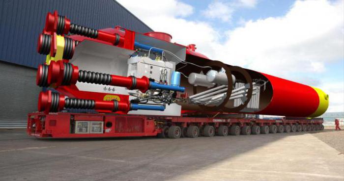
- Pelamis transducers - the so-called sea snakes - are hinged cylindrical sections. Under the influence of waves, an impromptu snake bends, setting in motion hydraulic pistons.
Advantages and disadvantages of wave energy
 Today, only 1% of the electricity generated is generated by wave power plants, although their potential is huge. The limited use of wave power plants is primarily associated with the high cost of energy received. One kilowatt of electricity received at a wind farm is several times more expensive than that generated at a thermal power plant or nuclear power plant.
Other disadvantages of using wave power plants include the following factors:
- Ecological. Covering a significant part of the water area with wave converters can harm the environment, because waves play a large role in the gas exchange of the ocean and the atmosphere, in cleaning the water surface from pollution.
- Socio-economic. Some types of generators used in wind farms pose a danger to shipping. This can force fishermen out of large fishing zones.
Despite the above disadvantages, in certain areas of the globe beyond the wave power plants the future, and here's why:
- Stations can act as wave suppressors, thereby protecting the coast of the harbor, ports, coastal structures from destruction.
- It is possible to install wave power generators of low power on the supports of bridges and piers, which reduces the impact on them.
- The specific power of the wind is a couple of orders of magnitude lower than the power of the waves, so wave energy is more profitable than wind.
- To generate electric energy through sea waves, hydrocarbon raw materials are not required, the reserves of which are rapidly depleting.
Geography of application of wave electric power plants
The use of wave power plants of insignificant capacities is used in obtaining power for small objects:
- coastal facilities;
- small settlements;
- autonomous lighthouses, buoys;
- research instruments;
- drilling platforms.
Already about 400 navigation buoys and lighthouses are powered by wave power plants - such as the floating beacon of the Indian port of Madras.
Portugal
The world's first large wave power plant with a capacity of 2.25 MW began to be operated in 2008 in the Portuguese region  the place of Agusador. The installation project was developed by the Scottish company Pelamis Wave Power, which concluded a contract with the Portuguese for 8 million euros.
Now at the station there are three wave energy converters - serpentine devices immersed one half in water. The length of each transducer is 120 meters, and the diameter is 3.5. The weight of the so-called sea snake is 750 tons. The waves drive the sections of the transducers, and the resistance of the hydraulic system contributes to the generation of electricity, which is transmitted via cable to land (the station is based 5 km from the coast). Currently, work is underway to increase the capacity of this wave of the station from 2.25 MW to 21 MW: it is planned to add another 25 converters. In this case, the installation will provide electricity to 15 thousand houses.
Norway
Pilot wave waves were first put into operation in 1985 in Norway.
One of them, with a power of up to 500 kW, is a pneumatic wave installation in which the lower open part of the chamber is immersed under the lowest surface layer of water.
The second power is 450 kW. Here, the effect of a wave running on a 147-meter confuser slope (a flat conical surface) is applied. The narrowing channel is located in the fjord, and the turbine water intake rises 3 m above mean sea level. The installation, located on the shore, eliminates the difficulties with its repair and maintenance.
Australia
One of the most successful projects in the field of processing ocean wave energy is the Oceanlinx turbine-type power plant operating in the waters of the Australian city of Port Kemble. After reconstruction and refurbishment, begun in 2005, the station was re-launched in 2009.
The principle of operation of Oceanlinx is to rotate the turbines with compressed air coming from a special chamber. The design of the station is cumbersome, and due to the severity of its weight, it stands at the bottom without violating its structure. About 1/3 of the entire structure, and this is almost 15 meters, protrudes above the surface of the water.
An important advantage of this type of wave station is the production of a predicted amount of energy. Platforms work due to disturbance of the ocean surface, not the waves themselves. This allows you to determine the weather conditions affecting the amount of energy generated, 5-7 days in advance. Oceanlinx has a capacity of 1 MW, and consumers receive about 450 kW of electricity.
 The correct and efficient operation of the city, and especially the public utilities, depends on reliable technology. an example of this.
The refrigerator broke and you drag it to the dump? Do not rush - read it!
You have a lot of rice husk, and nowhere to escape from it? The necessary material on the link.
Russia
The use of wave energy in Russia takes only the first steps. More recently, a wave power plant similar to the Portuguese one was experimentally launched on the Gamow Peninsula in the Primorsky Territory. The tests took place in Vityaz Bay at the marine experimental station "Cape Shulza". The initiators of this idea were scientists of the Ural Federal University and researchers of the Pacific Oceanological Institute at the Far Eastern Branch of the Russian Academy of Sciences.
Tests have shown that wave energy has great prospects. 
Concerns about starting this station caused:
- possible damage to the generator from the waves acting on it;
- traffic safety of fishing trawlers in the immediate vicinity of the station.
At the same time, the wave installation developed by Russian specialists, in addition to the main task - generating electric energy, can carry out a number of additional functions:
- become a wave suppressor, protecting coastal structures;
- make automatic protection of maritime borders.
It is necessary to develop wave energy in Russia. However, the existing hydrocarbon reserves, worked out, time-tested, mastered to the smallest detail technology of traditional power generation, cast doubt on the profitability of using large-capacity wave power plants. Wave power plants along with are likely to become the necessary step forward in the energy sector of which we all wait so long.
It makes sense to use alternative energy in sparsely populated areas of the coast of the Arctic Ocean, Primorye, and the Far East.
A life-saving way of generating energy. But I got the impression that the shortcomings presented in the article significantly alter the advantages.
On the other hand, I fully admit that over time, experts will find a way to improve wave power plants, and it is too early to categorically talk about the pros and cons of these energy converters. The experience of putting them into practice is too short and small.


